Scoreboard Construction
Introduction
With the availability of powerful and cheap micro controllers, it’s relatively easy to design and build an electronic scoreboard. The Raspberry Pi micro controller has everything that is needed. The internet is full of design examples, code snippets and programming libraries.
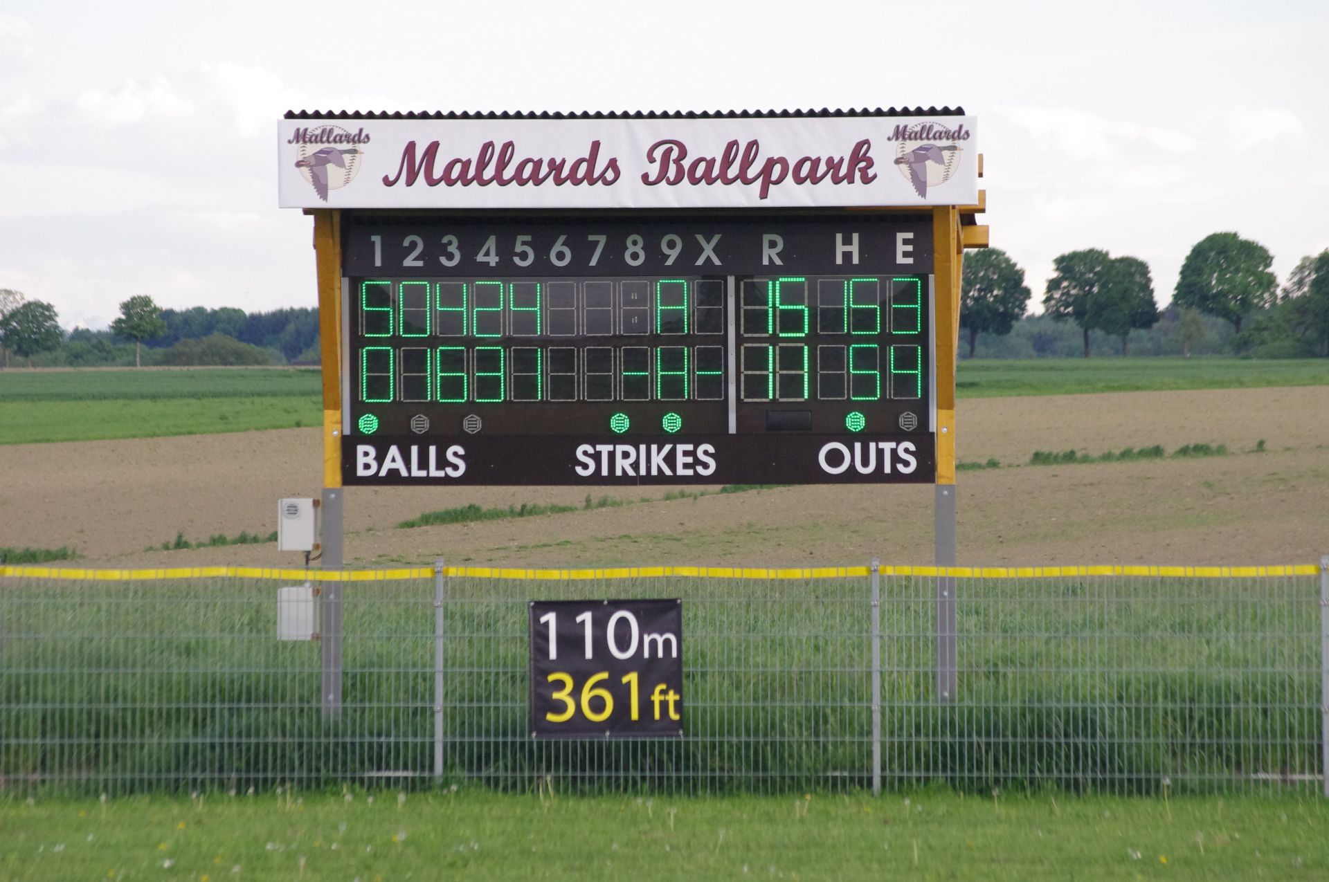
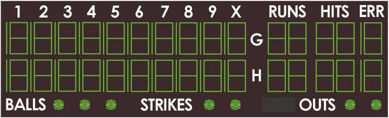
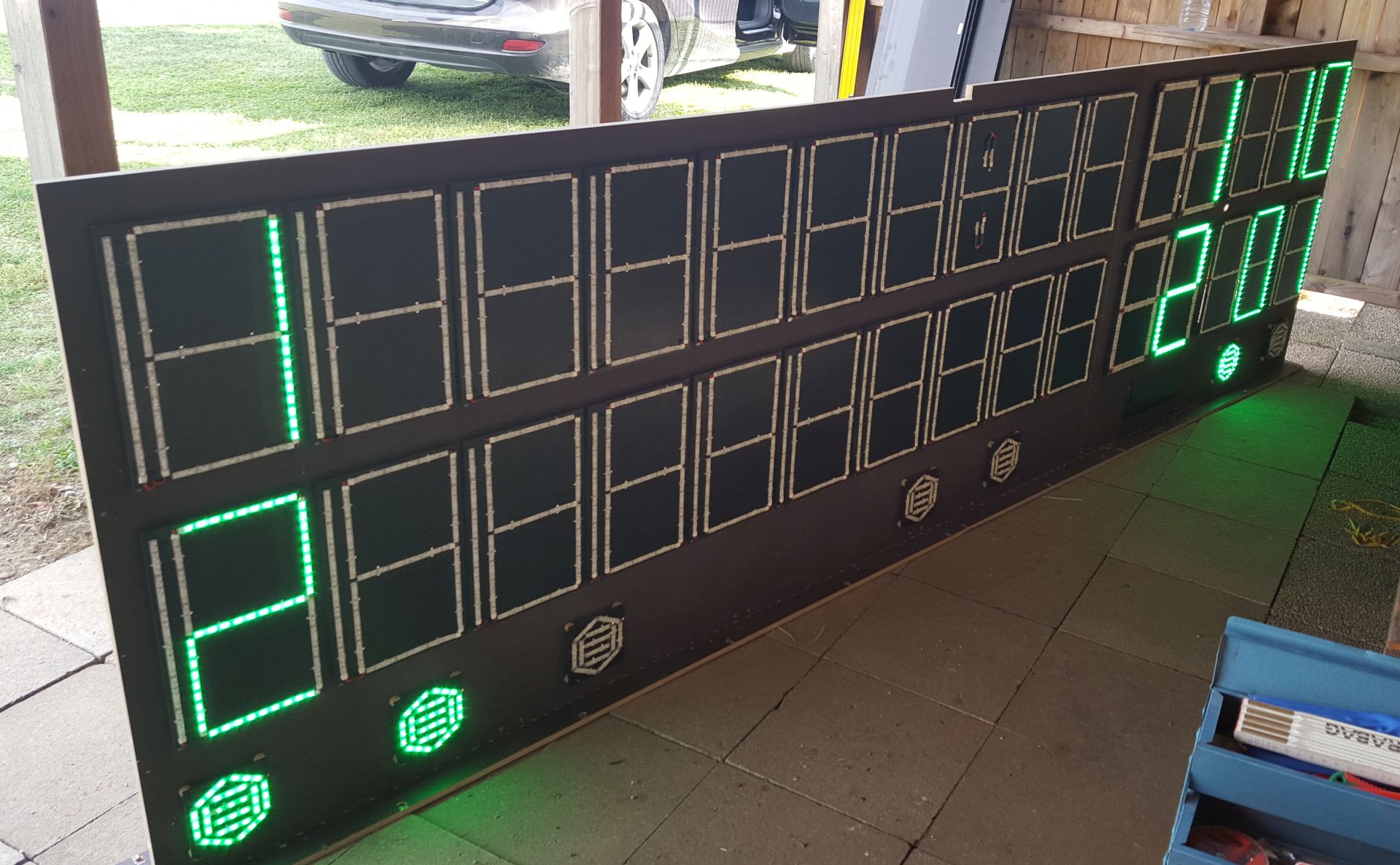
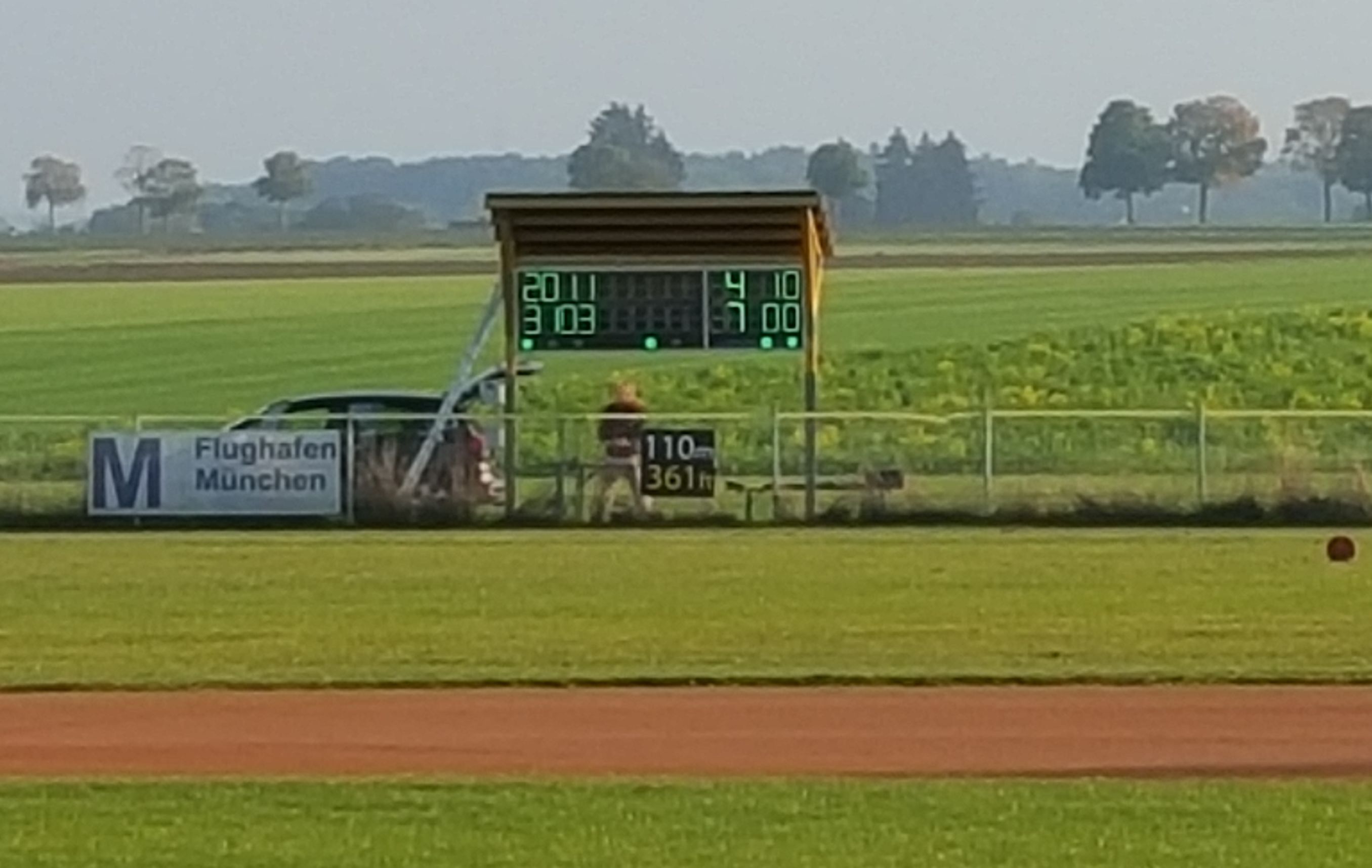
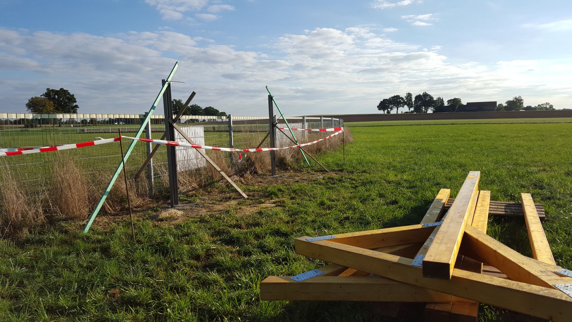
Initially, I wanted to build a simple scoreboard to only display the summed up runs, innings and balls/strikes/outs. But let’s face it – a complete scoreboard with all innings is so much cooler. So my small project grew from this

to this:
The following descriptions are not intended to be a step by step instruction. See them as a source of inspiration. Where possible, I’ve published my documentation and files. Especially for the the mechanical design and the housing I didn’t always document the construction, as I mostly went forward using what I had available and improvising.
Everything here is made available free of charge, under coverage by the GNU General Public License. However, if you do use the information to build your own scoreboard, please make sure that the Erding Mallards are mentioned.
You can contact me through the contact form.
Anders Lind, Erding, January 2016
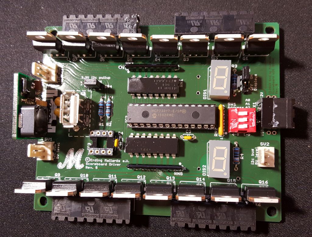
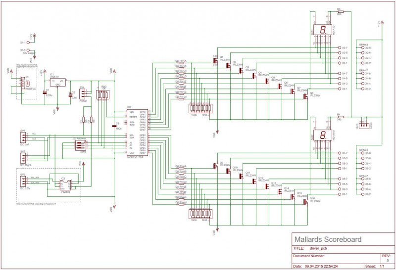
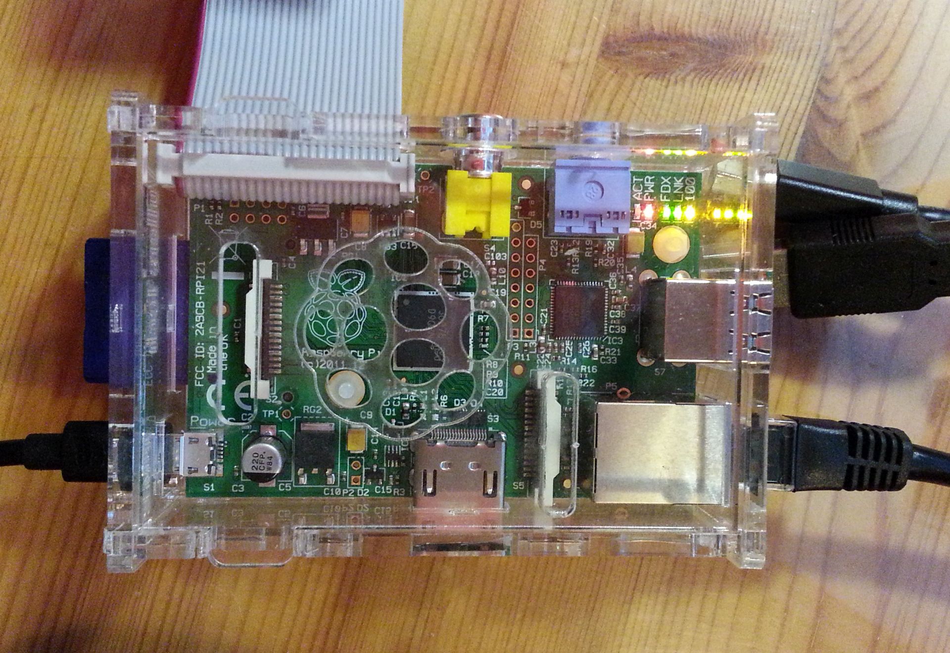
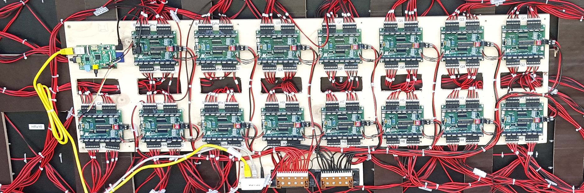
I didn’t want to spend money on a professional layout software. Using the free version of Eagle, a PCB of the size 10 x 8 can be designed, so that’s the size I chose. Instead of one large I made 15 small double-sided PCBs, each one holding a MCP23017. Each board is powered by 12V and generates its own 5V supply using a simple 7805 voltage regulator. The Raspberry Pi is powered from one of the driver boards, which gets a pin compatible switching power converter instead of a 7805, which otherwise would require a large cooling flange. The LED strips are switched using STP16NF06L power MOSFETs, which have a particularly low resistance and thus require no cooling.
Schematic (click for a PDF file):
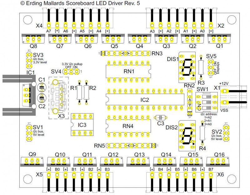
Board mounting layout (click for a PDF file):
Zip file with manufacturing data
PCB table of content (PDF file)
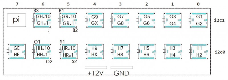
Each board drives two digits. As the digits for runs and hits only require 7 signals instead of 8, the additional 8 signals are used to drive the lamps for balls, strikes and outs, as well as the colon.
Driver usage (click for a PDF file):
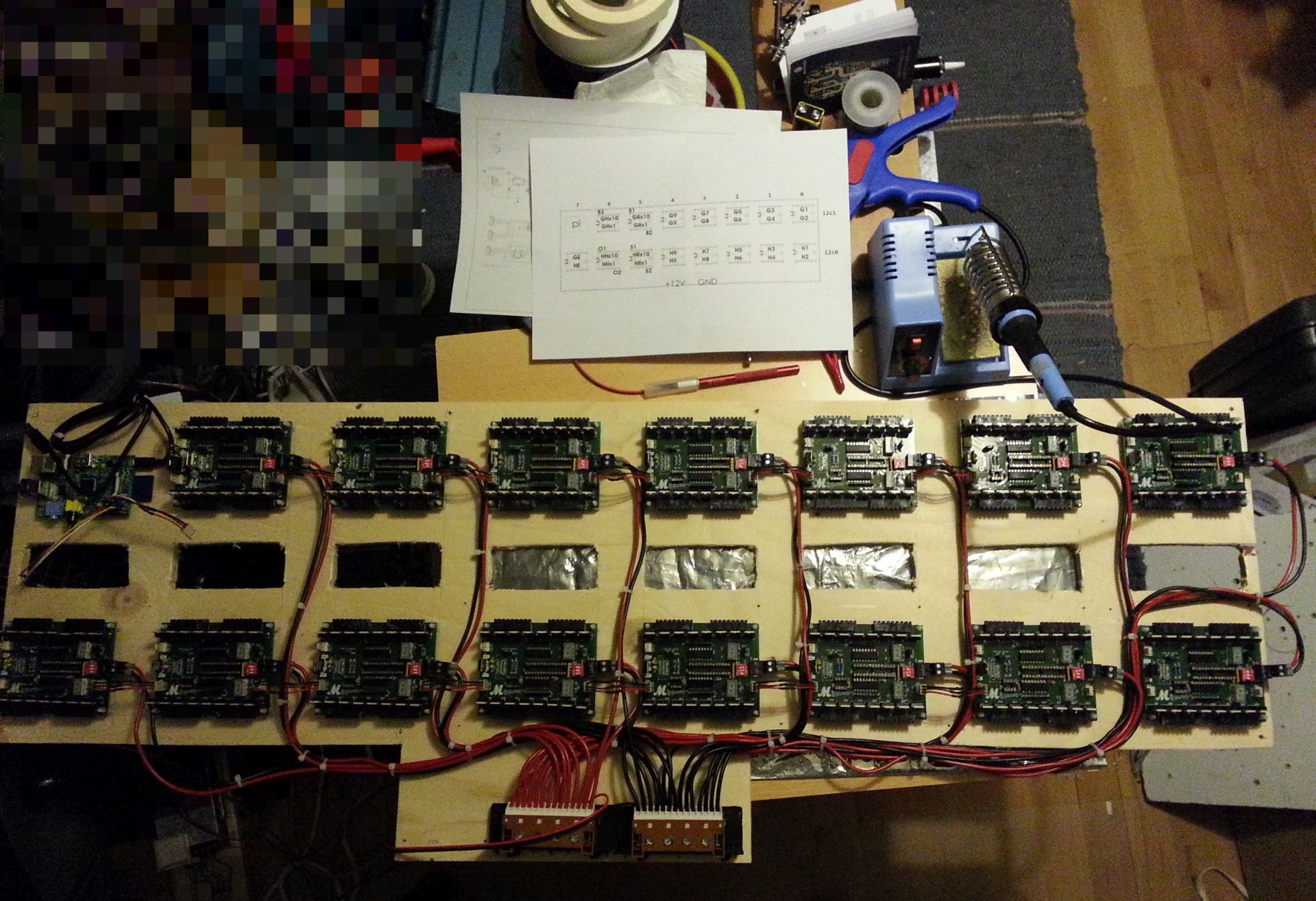
I ordered and built 16 boards, so that I have one in reserve in case one breaks.
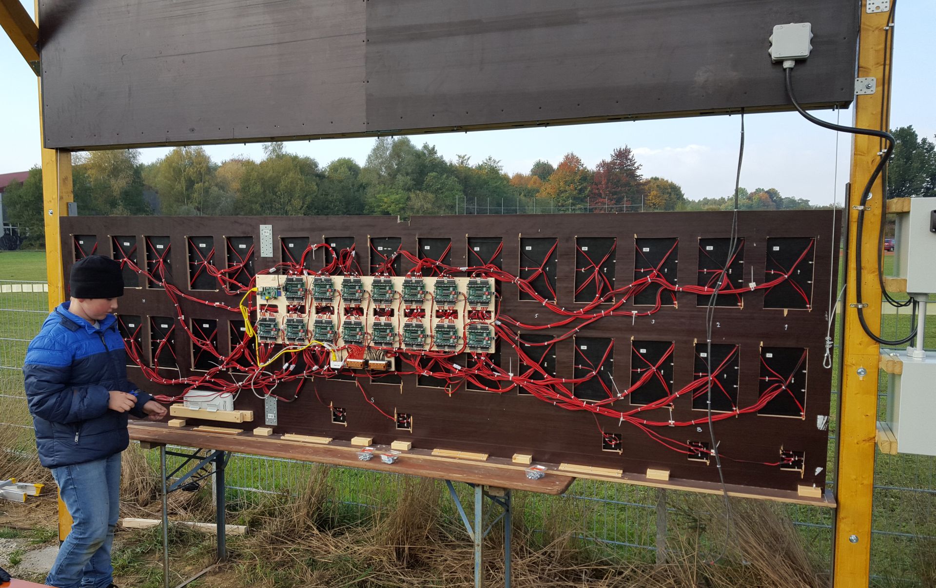
For the programming and testing, I included two 7-segment displays on the boards. This proved to be very useful, as I could assemble the entire control system on a plywood board with 1 m length and could check everything out without having the large LED digits and the housing available. The displays can be de-activated through jumpers.
The board also has a socket for an i2c repeater of type P82B96, which is only mounted on the first board of each i2c bus string. Each board has two pull-up resistors for the bus, which can be activated or deactivated through a jumper. This proved to be important, as I had to try out various combinations of pullup resistors before the buses were stable. At the end, around every second board had to have a pull-up.
To simplify the assembly, I chose to use connectors and receptors from AKL. One could also use skrew terminals, but it would be a bit of a pain having to connect 240 individual wires at once. I also use connectors for the 12V power supply connections.
After soldering all the components to the boards, I cleaned them (including the Raspberry Pi) thoroghly, covered all the jumpers and sockets with tape, and coated them with enamel. After drying, I removed the tape and inserted the ICs in the sockets.
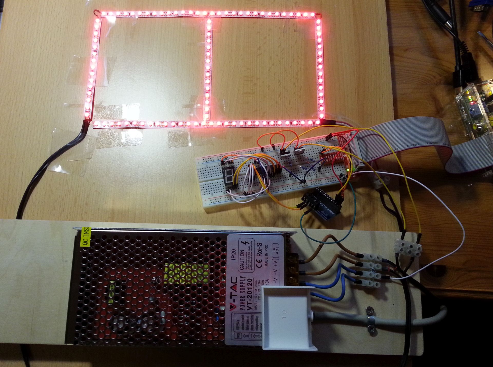
Usually, scoreboards and other signes use red numbers. I purchased a 5m roll of red LED strips using 3528 diodes (i.e. diodes with an emitting surface of 3.5×2.8 mm), glued them to a plywood plate and tried it out. It looked OK at home, but when I tested it on the field in sunlight, it turned out that the numbers were only visible at a distance of 50 or 60 meters. The light output was simply too weak. I could of course opt for larger 5050 diodes, but that would exceed my power budget.
Luckily, the human eye is much more sensitive to green light than to red, by a factor of around 10. A new trial using green LEDs was successful, this time I could easily read the number across the entire field.
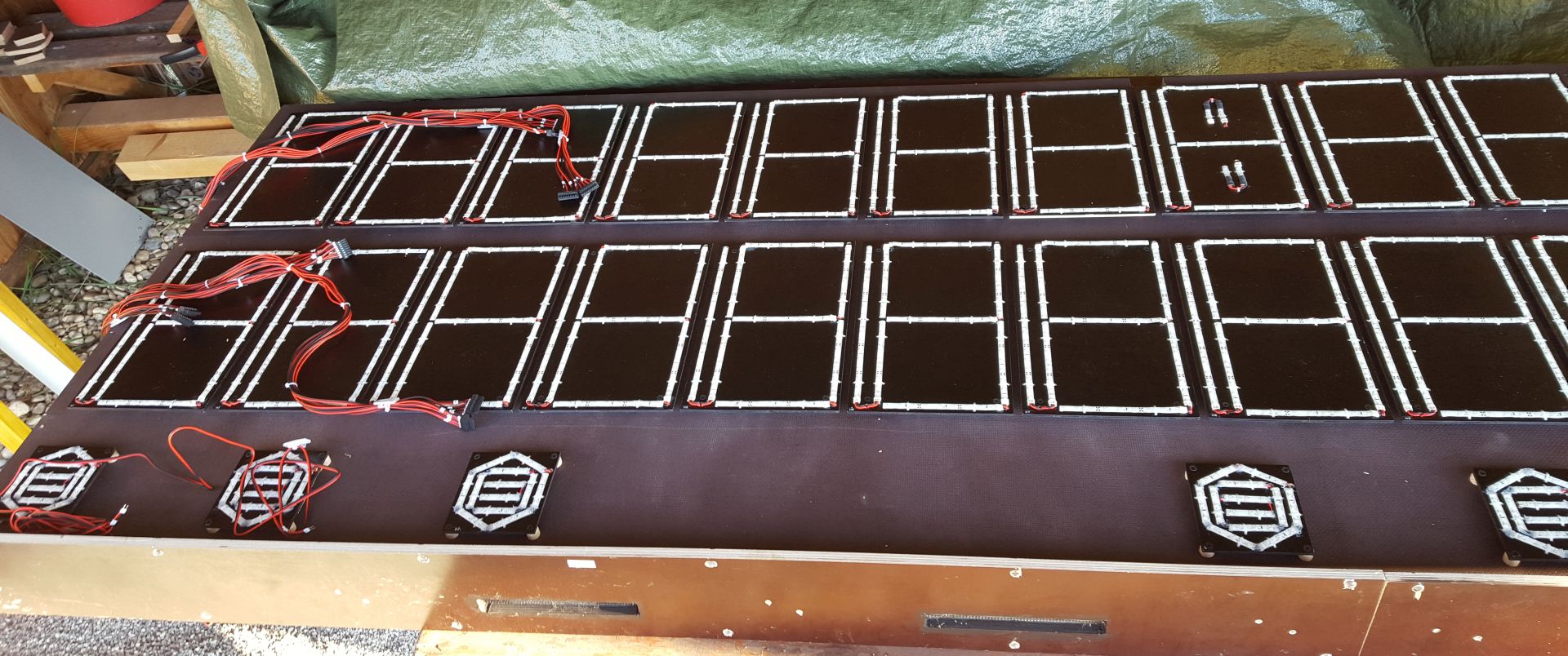
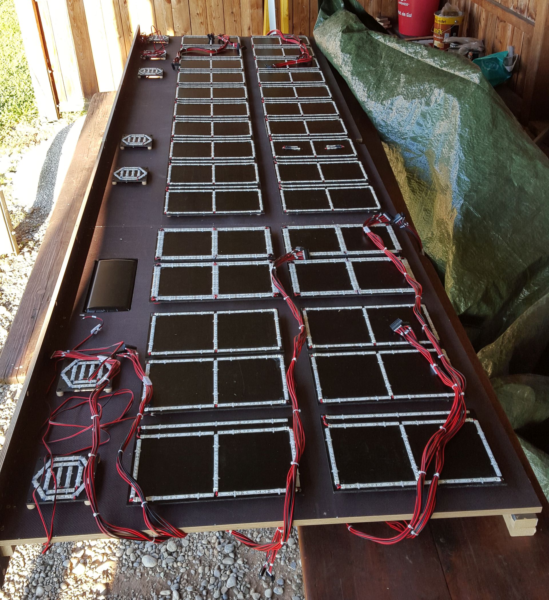
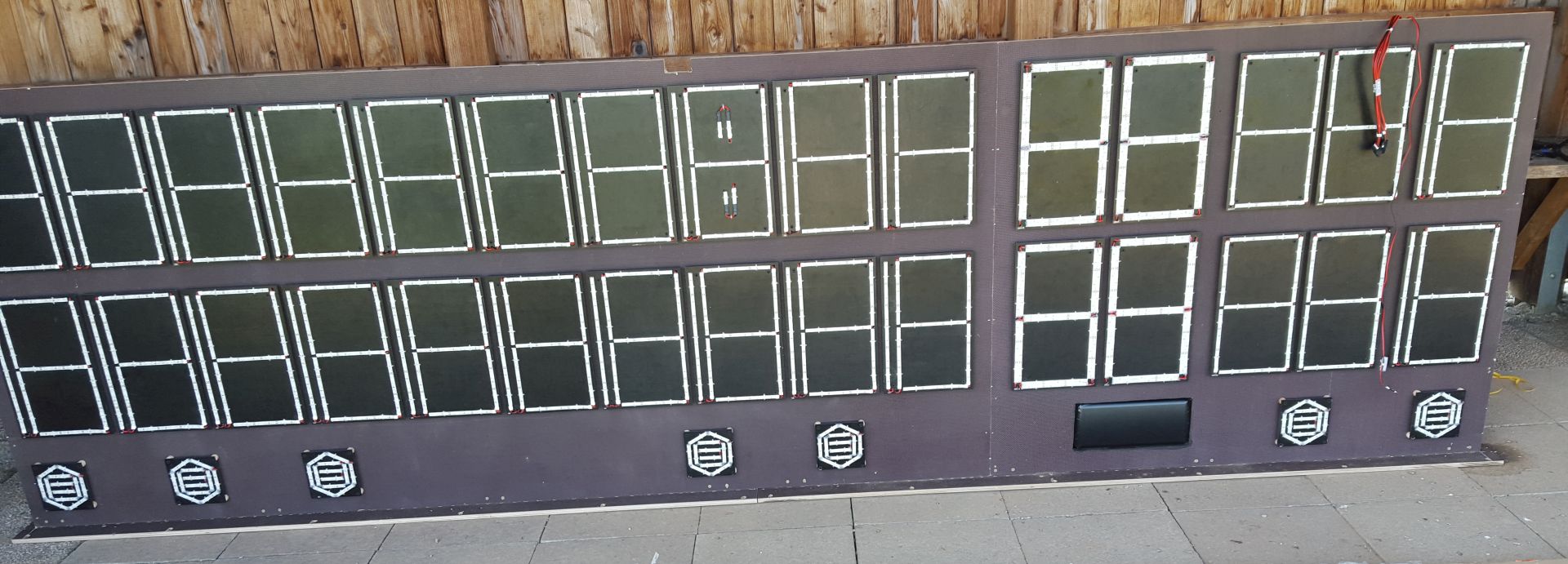
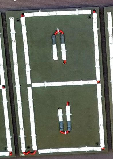
Each number was built on a 4mm thick phenolic plywood sheet. I drilled a lot of holes to fasten the LED strips with cable ties, in case the adhesive should weaken over time. I used strips with 60 LEDs per meter, which corresponds to 3 LEDs for every 5 cm. The strips are sealed with silicone for weather protection. Each segment of a number consists of 3 segments, i.e. 9 LEDs. Soldering the segments to their cables was a lot of work:
- Remove the silicone coating at one end using a sharp knife.
- Clean the soldering surfaces from remaining silicone.
- Apply solder tin to the surfaces.
- Strip the cables to around 4 mm and apply solder.
- Press the cables to the soldering surfaces and solder them in place.
- Strip the other end of the cable and use a 9V battery to test the connection.
- Cut shrink sleeving to10mm length and shrink it in place to seal the connection.
Before that, I cut all the cables to the correct length.
Signal cabling (click for PDF file):
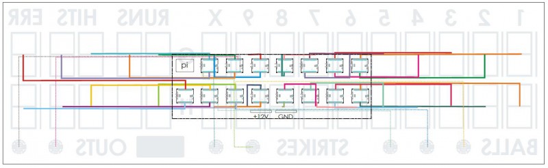
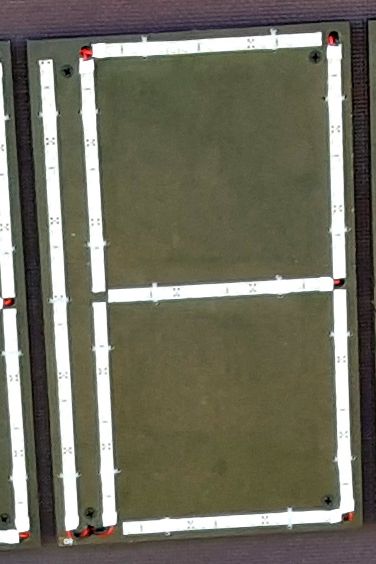
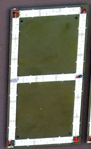
After mounting the LED strips to the sheets, I fastened the cables on the rear using cable ties, at the same time mounting the cable ties holding the LED strips. I then used more cable ties to form a bundle with equal cable lenghts, and then stripped the ends again and use the 9V battery to identify the segments. I used self-adhesive cable markers. Finally, I crimped sleeves to all cable ends.

Bill-of-material mounting plate (PDF file)
Drill drawing of the digit sheets (click for PDF file): 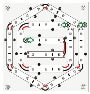
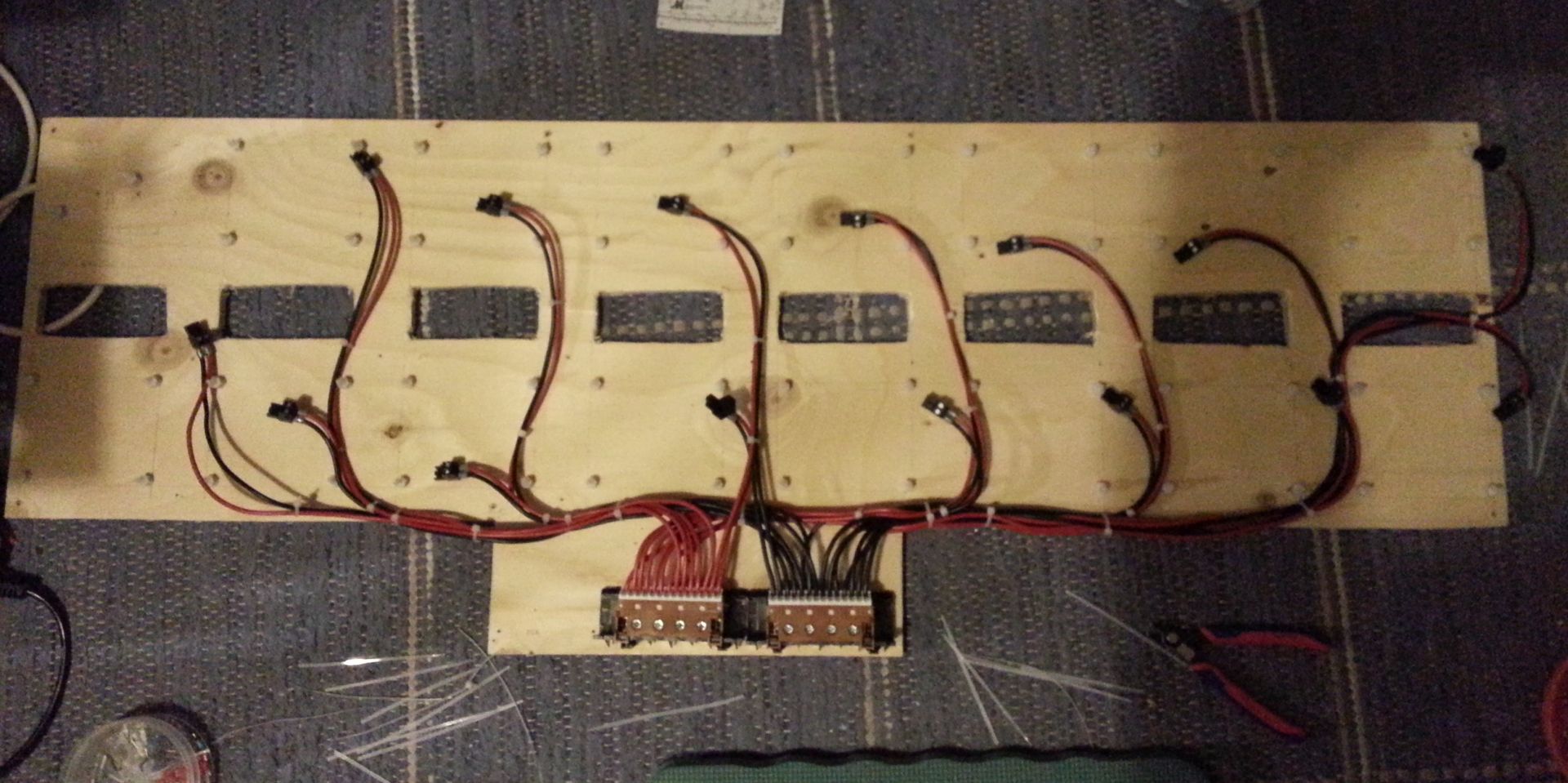
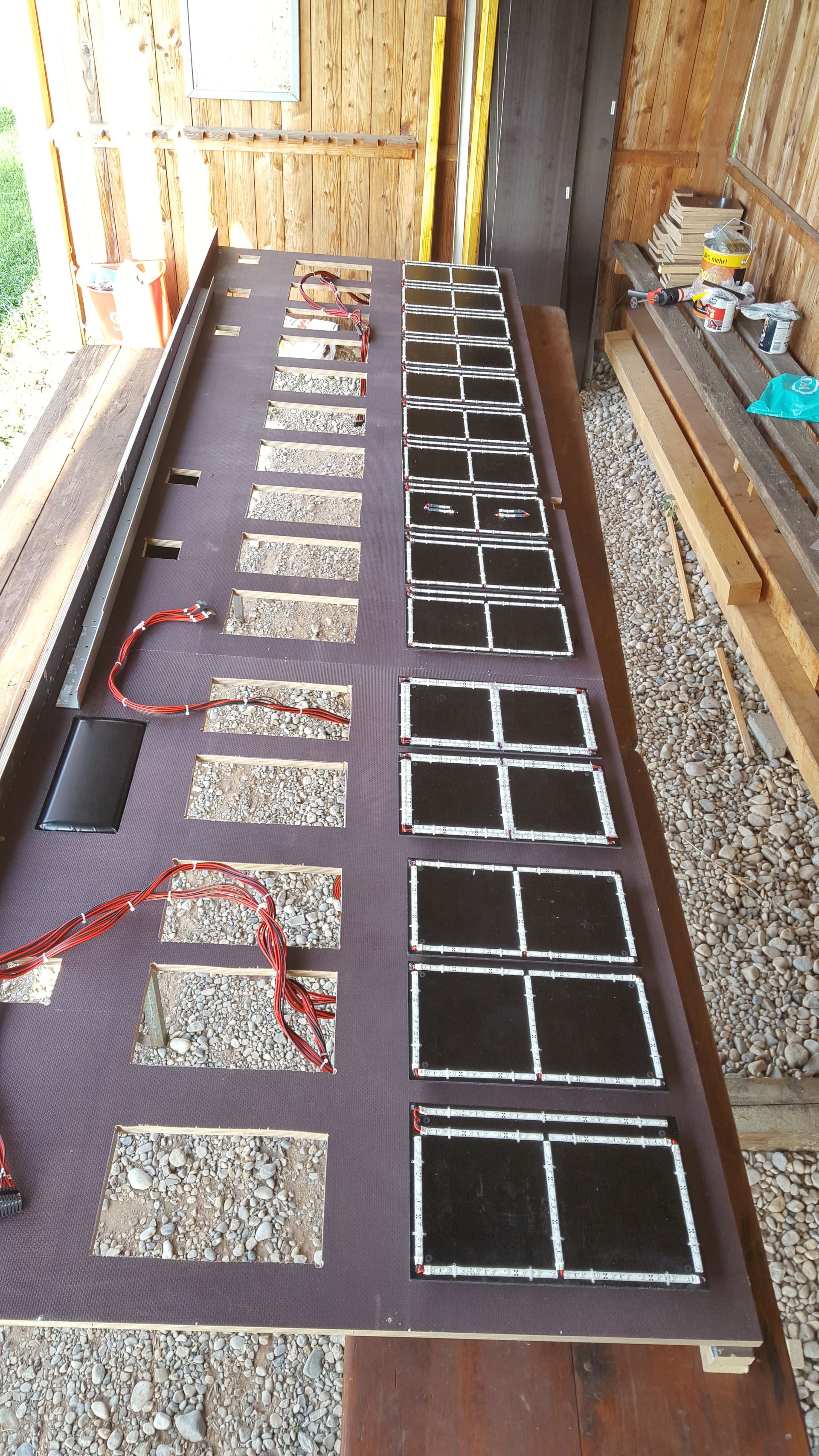
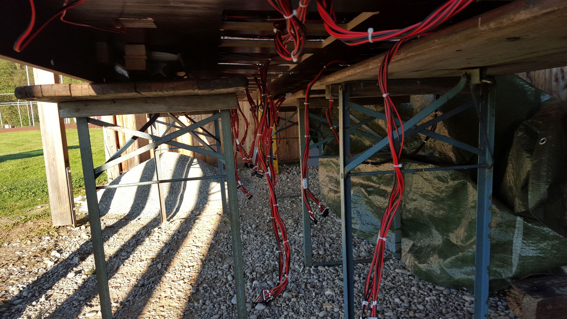
The driver boards and the micro controllers are mounted on a 10mm strong plywood plate. The plate has several rectangular cutouts for the cabling. Two power rails and the power splitter for the WLAN module are also mounted here.
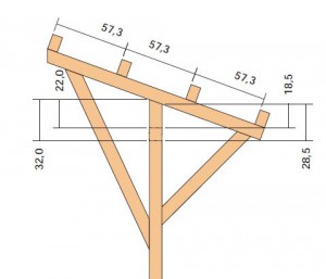
I designed the scoreboard for a width of 3.46 meters. This allowed me to use 4m beams for the roof construction, the longest length available at the hardware store. In retrospect, an additional 1/2 m would have been better, since I find the digits to be a bit to close to each other for perfect visibility.
As main support for the digits I joined two 16mm thick phenolic plywood sheets together. I cut out large openings to both save weight and for easier assembly of the cabling. I made wooden spacers, 10mm thick by drilling a hole through knothole fillers – much cheaper than plastic spacers. But I had to drill around 160 of them. Using the spacers, the digits were screwed on to the main support using black screws. The plywood plate came on the rear side.
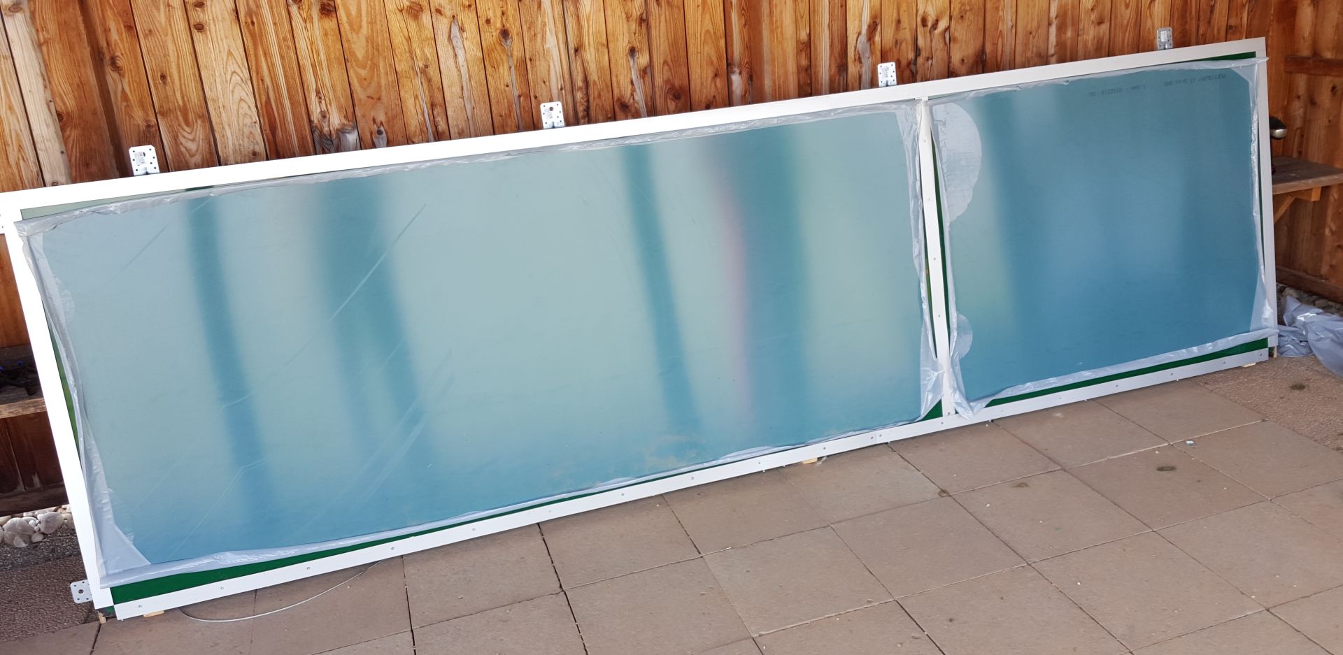
The housing was constructed of 12mm thick phenolic plywood sheets on a wooden frame. I hadn’t quite accounted for the weight, the entire think requires two persons to carry. One could surely do thing differently, depending on the local requirements. I chose a variant where the main support is attached to the bottom surface and the entire thing is inserted from below. Two aluminium profiles are used to guide the assembly. For service, the mounting screws can be removed and the entire assembly be slid out, without having to dismantle the entire housing. Two steel wires prevent that the assembly falls to the ground. Two persons are definitely needed to assemble and disassemble it though.
The front consists of two 3mm thick acrylic glass sheets. They are not screwed in place, since acrylic glass has a high therman coefficient and will shrink and grow with the ambient temperature. One has to account for 5mm per meter. So I used aluminium profiles and regular window insulation (P-profile) to squeeze them in place.
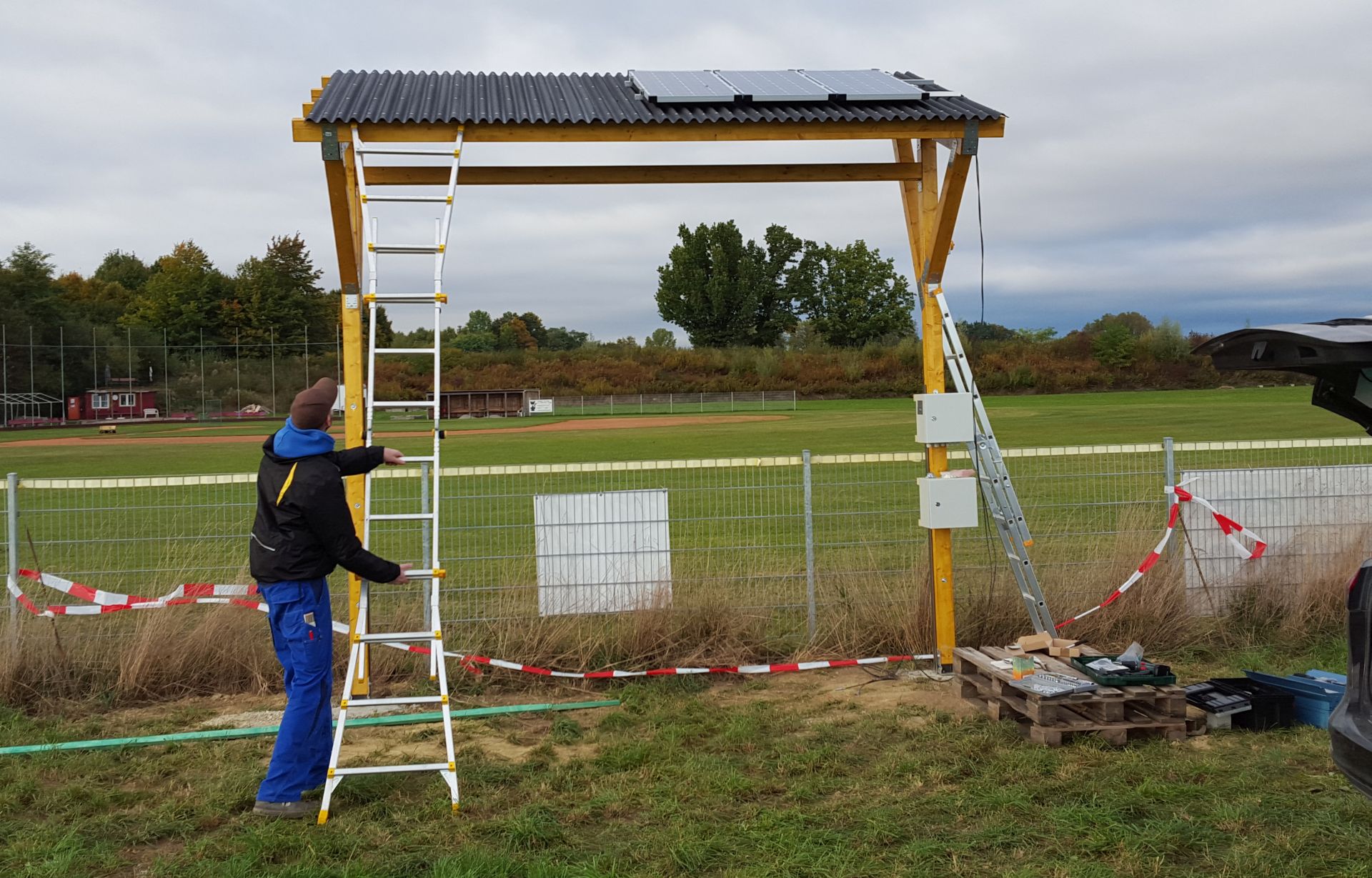
To avoid too high temperatures in the housing, I attached two 120mm fans in the upper corners. They are attached to 12V through a 40 °C thermal switch. Fresh air is sucked into the housing through filtered vents in the bottom side.

The mounting assembly is constructed of 10x10cm thick wooden beams. Two vertical beams are bolted to two 3m long steel U-beams (U120), set 1m deep in concrete. Shorter beams angle out at around 2m height to support the roof construction. Four 8 x 12cm beams form the roof support. The roof itself is made of corrugated bitumen sheets, fastened with nails. Another 10 x 10cm beam is fastened between the vertical beams, holding the scoreboard with 4 angle irons. The scoreboard is also fastened with 2 angle irons on each side.
Drawing of the side assemblies (click for PDF file):
First the power must be switched on. The main switch is located on the upper power cabinet and has a detachable knob acting as key. The Raspberry Pi boots and initiates the WebIOPi software. When the boot sequence is finished, a welcome message is displayed on the scoreboard.
The scoreboard operator, using a tablet, smartphone or laptop, connects to the WLAN network provided by the access point and then opens the control page. This is only accessble by entereing the correct IP address. Each time the page is refreshed, the system time of the scoreboard is synchronized with the time on the client.
This is what the control page looks like:
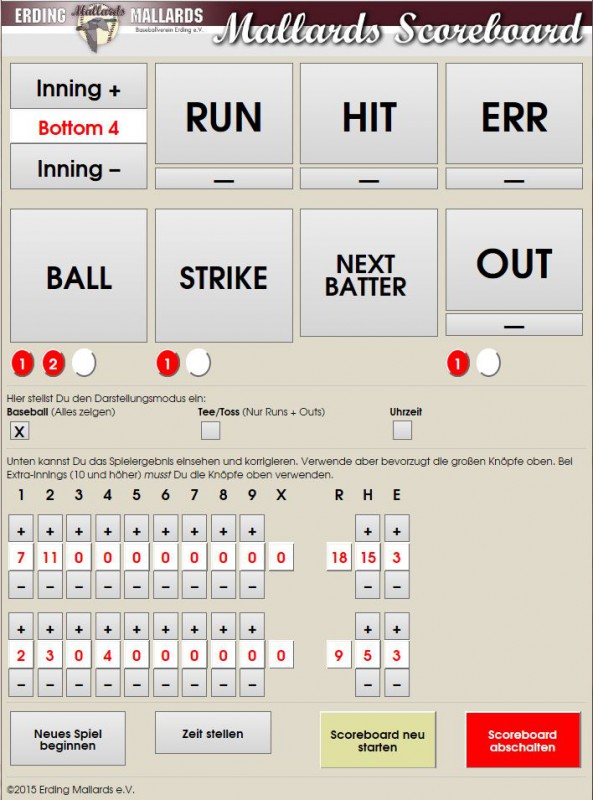
It’s divided into four sections. On the top, the main control buttons for Innings, Runs, Hits, Errors, Balls, Strikes, Outs and Next Batter are located. The current Balls/Strikes/Outs are indicated as colored circles. The innings counter shows the current half-inning as a text. The innings counter begins with „Pre-Game“, at which stage the other buttons are inactive. By clicking on „Inning +“ and „Inning -„, the corresponding half-inning run digit is activated. When Hits or Errors are updated, the digits will flash 5 times. Up to the 7th inning, an „A“ for Away and a „H“ for Home is shown in the 9th inning column. A dash in column 8 and X indicate which team is at bat. In the 8th inning, only the „A“ and „H“ are displayed in the X column.
The next section has three buttons, controlling the display mode:
- Baseball: all counters are active
- Tossball: Hits, Errors, Balls and Strikes are inactive and not displayed
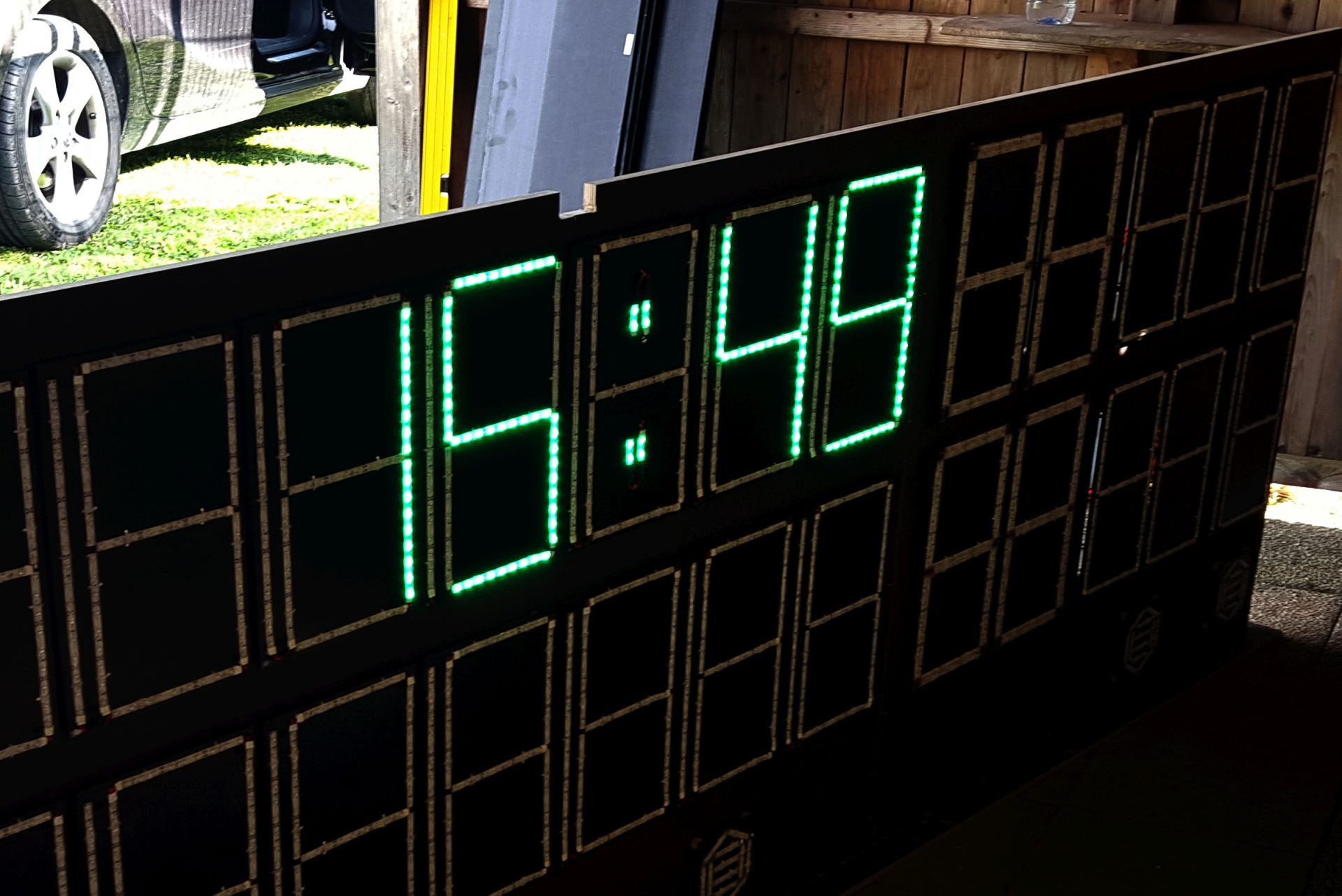
- Uhrzeit: The current time is shown
- HOMERUN: shown as a marquee (new in version 3)
The operator can switch between the modes anytime without any loss of data.
In the third section, the individual innings with their Runs, the summed up Hits and Errors are shown. This area can be used to adjust the results without having to step through the innings with the main buttons.
Further down, there are 4 buttons:
- Neues Spiel beginnen: Start a new game. After confirming the popup, all counters are reset and a new game started.
- Zeit stellen: Should the automatic time synchronization fail, this can be used to set the time.
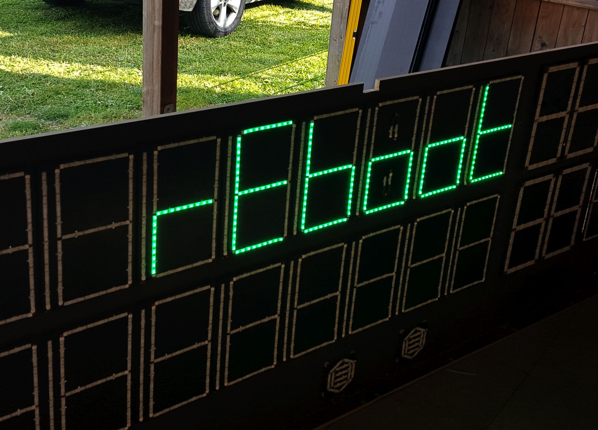
- Scoreboard neu starten: This will reboot the Raspberry Pi. All counters ar reset. The scoreboard will display „reboot“ during the reboot process.
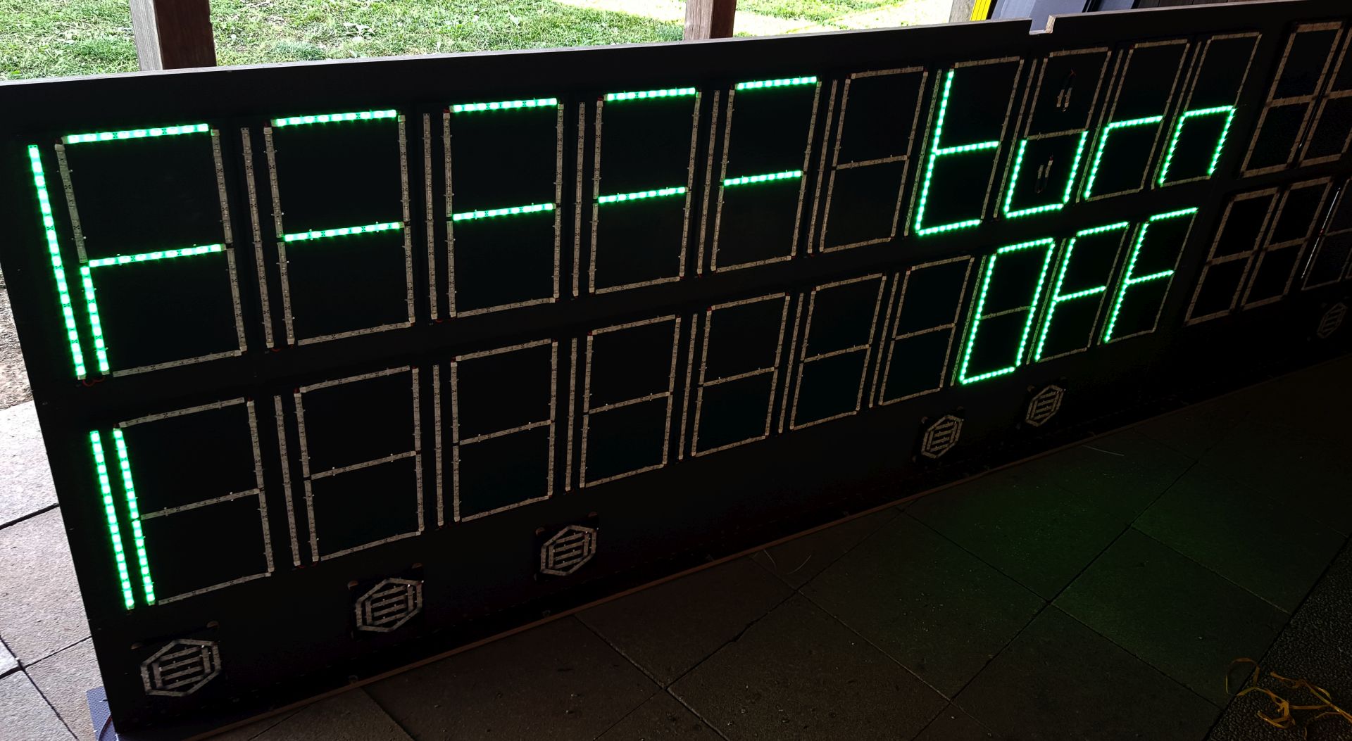
- Scoreboard abschalten: This button is used to turn off the scoreboard after the end of the last game. The display will show „Turn off“ to remind the operator, that the main switch must be turned off.
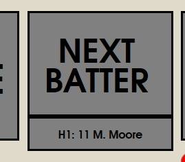
New in version 3:
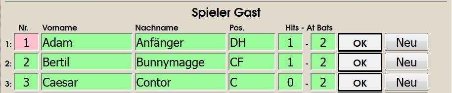
I have added a new section, where information about the 18 batters can be entered. If information was entered (the test is if the jersey number is anything else than 0), the player information is displayed for 10 seconds when the „Next Batter“ button is clicked. Under the „Next Batter“ button, I added an additional button, which displays the next batter information. By clicking this button, the user can scroll backwards through the batting order. Entry fields:
- Jersey number
- Given name
- Family name
- Field position
- Hits
- At Bats
This was largely implemented using Javascript. The player entires are stored in the browser session and retained, until the browser session is closed. The entry fields are color coded:
- White: data is present, but possibly not yet sent to the scoreboard. This can happen, if the scoreboard is restarted.
- Green: the data has been sent, using the „OK“ button.
- Red: new data was input and not yet sent.